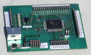
The Cypress (former Anchor Chip) AN2131 EZ-USB microcontroller contains an improved 8051 plus a USB serial interface engine. The internal 8kByte RAM (Code, Data) can be written from a PC via the USB bus to download the firmware to the chip. Therefore no flash or other non-volatile memory is required. Firmware update is as easy as restarting the PC application.
My first project using the EZ-USB microcontroller was the "EZ1" test board in 2001 with two MAX521 8 channel DACs, a MAX127 8 channel 12 bit ADC (both with I²C interface), a RS232 connector and one for the Infineon FingerTip sensor as well as two LEDs. If you don't have JTAG for debugging, two LEDs is the absolute minimum to trace the program execution.
In the meantime I did several other projects using this microcontroller.
The EZ1 board lacks connections for general purpose digital signals (e.g. to control an OLED). Therefore a new board was required. Contrary to the EZ1 it holds the 80 pin version of the microcontroller. All signal pins are connected to pin sockets. Port A is also connected to eight LEDs (with a driver chip).
The new board already proved useful to control an OLED module (ELV ODM100). The image shows the display on the left and the EZ-USB breakout board on the right. The image on the display is only shown partly due to the short exposure time of the camera. The ribbon cable is used to "convert" the pins of the display module to sockets which can be connected with stripped wires to the breakout board (colored wires). ELV offers source code to access the OLED. Only a few changes were necessary to get it working for the 8051. More work helped to speed up the port access and therefore image setup.
Files: Schematic PDF, Eagle Schematic, Eagle Board


Keine Kommentare:
Kommentar veröffentlichen